
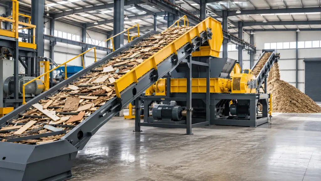
Positioned as the first processing stage in a Waste Tire Granule Line, the Double-Shaft Shredder uses two sets of intermeshing alloy blades rotating at low speed to shear and tear feed material, reducing whole tires into shreds for downstream processing.
Whole tires contain dense rubber and heavy bead wire bundles, generating intense shear resistance at the point of initial engagement. Insufficient shaft torque causes the cutting teeth to stall against the bead wire, tripping the drive motor and damaging the internal gear train.
Sizing the drive assembly requires determining the peak shear resistance needed to cut the tire, calculating required shaft torque, selecting the hardened gearbox ratio based on target speed, and back-calculating motor power. Motor sizing dictates throughput rate, but shearing bead wire depends entirely on gearbox output torque.
| Drive Component | Engineering Sizing Criteria | Failure Prevention Target | Duty Evaluation Criteria |
|---|---|---|---|
| Drive Motor | Matches rated shaft speed and throughput targets | Prevents winding burnout under low-speed high-load stalls | Calculates input power from peak cutting torque and shaft speed |
| Hardened Gearbox | Handles shock loads and high reduction ratios | Prevents gear tooth breakage, pitting, and output shaft fracture | Verifies multiplied torque exceeds tire bead wire shear limits |
| Heavy-Duty Shaft and Alloy Blades | Intermeshing geometry applies cutting and tearing force | Prevents edge chipping and material slippage from wear | Blade radius and thickness define shear force and shaft torque requirements |
| Electrical Control System | Monitors current thresholds and triggers auto-reverse logic | Prevents drive line damage during extended mechanical stalls | Configures overload response sensitivity and reverse cycle logic |
1. Tire Primary Shredding Shear Resistance and Shaft Torque Calculation
Cutting resistance combines tire carcass tear resistance and bead wire yield shear strength. As the two shafts counter-rotate, cutting load remains steady through the rubber tread, then spikes abruptly when the blades strike the steel bead bundle.
Shaft output torque equals blade turning radius multiplied by cutting force. Increasing the blade outside diameter raises tip speed, yet decreases tangential cutting force for a given shaft torque. Calculations must focus strictly on the peak moment of shearing the bead wire bundle; using average rubber tear values leads to undersized drives.
Sizing verification depends on blade performance when cutting solid bead wire. Once blade thickness is set, shaft torque must ensure a single tooth shears high-carbon steel wire at rated speed without dropping RPM, which would otherwise cause material slippage and collapse throughput.

2. Hardened Gearbox Selection and Motor Power Matching Principles
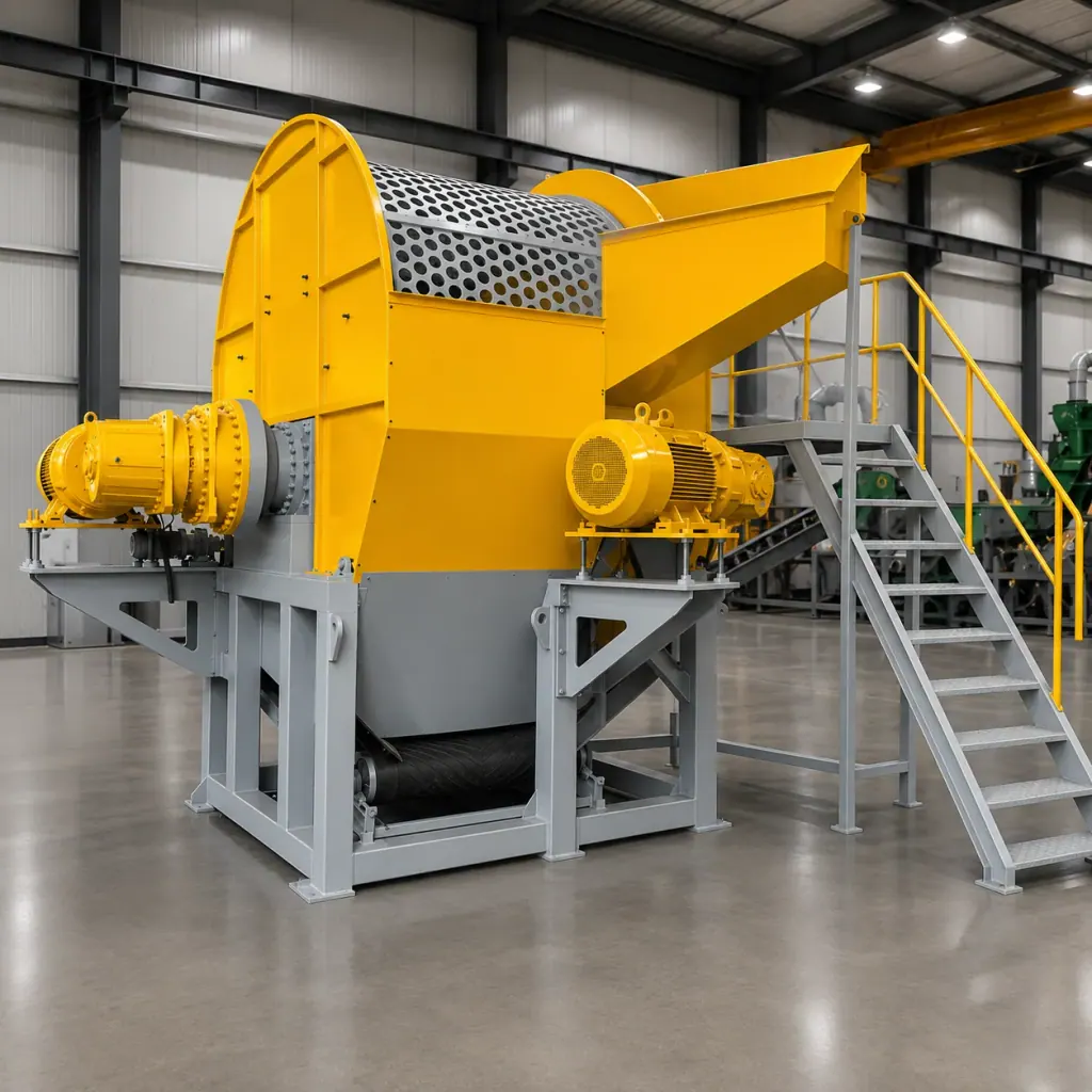
The drive train links the motor, coupling, gearbox, and shaft sleeves in series. The gearbox reduces motor speed while multiplying torque, generating heavy gear contact stresses. This duty requires hardened gearboxes with carburized and quenched tooth flanks to absorb reaction forces during cutting.
The reduction ratio determines shaft speed and torque multiplication. Too low a ratio leaves shaft speed too high and torque insufficient to cut bead wire. Too high a ratio drops shaft speed below target feeding rates, limiting plant capacity. Gear ratio selection must balance safe shaft speed and torque multiplication to overcome wire bundle resistance.
Motor power calculation follows shaft torque requirements. After establishing the torque and speed required to cut steel-belted tires, motor power is determined by factoring in driveline mechanical losses. Dual-drive setups using independent motors and gearboxes on each shaft reduce individual gearbox frame sizes.
3. Overload Reverse Logic and Drive Shock Redundancy Configuration
When non-deflated heavy tires or uncrushable tramp metal enter the chamber, instantaneous resistance exceeds motor rated torque. Electrical cabinets require current transformers to set overload trip points and response delay intervals.
If a stall pushes current beyond the trip threshold, the PLC stops shaft rotation, reverses the motors to discharge jammed material, and then resumes forward shredding. If multiple reverse cycles fail to clear the blockage, the system trips an alarm for manual intervention, protecting motor windings from sustained stall current.
Drive impact capacity depends on gearbox service factor. The mechanical torque capacity and thermal rating of the hardened gearbox must include sufficient safety margins to absorb energy spikes during reverse cycles and material re-engagement, preventing shaft and spline fatigue.
Machine in Action
FAQ
- Can jamming issues on a double-shaft shredder processing scrap tires be resolved simply by increasing motor power?
- Motor size determines power input rate, but shearing bead wire requires shaft torque. If the gearbox reduction ratio is inadequate, a larger motor still cannot deliver the required low-speed tangential cutting force without increasing the gear ratio or upgrading gearbox mechanical capacity.
- Can a double-shaft shredder in a Waste Tire Granule Line use bottom screens to regulate shred size?
- A double-shaft shredder serves as a primary coarse shredder, discharging sheared material directly beneath the cutting shafts. Screens cannot be fitted below the cutters, as cut bead wires and steel cords quickly plug the mesh; output size control is handled downstream by secondary shredders and screening units.
- Is a hydraulic drive or a mechanical hardened gearbox drive preferred for tire shredders?
- Mechanical hardened gearboxes offer high transmission efficiency and straightforward maintenance for continuous tire shredding. With an adequate application service factor and properly tuned reverse-protection logic, mechanical drives dependably manage coarse tire shredding shock loads.